SOLAR OFF GRID SYSTEM DESIGN AND SIZING


OFF GRID SYSTEM DESIGN AND SIZING

At off grid solar kits, we have the qualifications, accreditation and project experience, to deliver an Off-Grid solar system that exceeds expectations. We use proprietary, state of the art, solar performance analysis software, to design stand alone power systems, specific to location and power usage. You will not find a more capable team of off grid solar design engineers. If you desire a system that performs as it is suppose to, and delivers all year round, contact us now.

3 kw energy usage.PNG

3 KW SYSTEM DESIGN SPECIFICATIONS

Our 3 kw system is a strong performer for a small house. Coming standard with a 3kw continuous rated off grid inverter with a large surge capacity, this unit will run general appliances listed in the table to the left comfortably. Contact us for a site specific design for your location.


6 kw energy usage.PNG

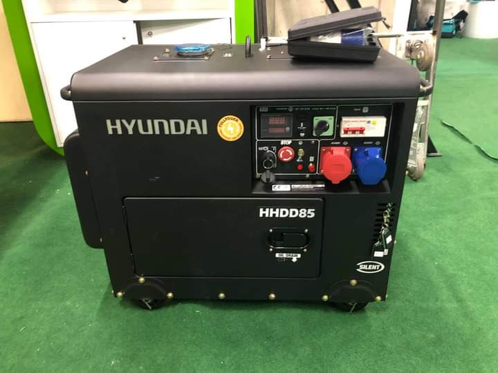
6 KW SYSTEM DESIGN SPECIFICATIONS

Our 6 kw system is a strong performer for a small house. Coming standard with a 6kw continuous rated off grid inverter with a large surge capacity, this unit will run general appliances listed in the table to the left comfortably. Contact us for a site specific design for your location.


9kw energy usage.PNG

9 KW SYSTEM DESIGN SPECIFICATIONS

Our 9 kw system is a strong performer for a small house. Coming standard with a 3kw continuous rated off grid inverter with a large surge capacity, this unit will run general appliances listed in the table to the left comfortably. Contact us for a site specific design for your location.


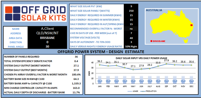
Correct sizing by an experienced designer is crucial to a reliable off-grid power supply.

Our design team takes into account many factors including:

  • Site specific irradiance levels

  • Max and minimum temperatures

  • Panels orientation & tilt

  • Shading

  • Continuous load demands

  • Surge demand

  • Time of use

  • System inefficiencies

  • De-ratings

  • Max charge/discharge rates

  • Power factor

  • Usage autonomy

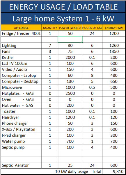
We size our systems around your power consumption, ensuring the battery bank has capacity for bad weather periods and the solar array can cover your usage, even during your area’s average worst month conditions.

To do this the first step is to assess your power requirements. To obtain a preliminary sizing our first questions will relate to the large consumers i.e. Hot water, cooking elements/ovens, air conditions, large pumps and workshop tools such as welders etc.

From this information and experience we can calculate general systems sizes and price.

Other indicators of usage may come from what you’re using in your current grid connected property, with your usage detailed in the bill. If/when more information is available we can carry out a load assessment that calculate power consumption from your appliances power usage and estimated run times.

With an existing system, running off a generator, we can supply energy usage meters to accurately record your actual power consumption.

Below are some examples of systems may be suitable for you.

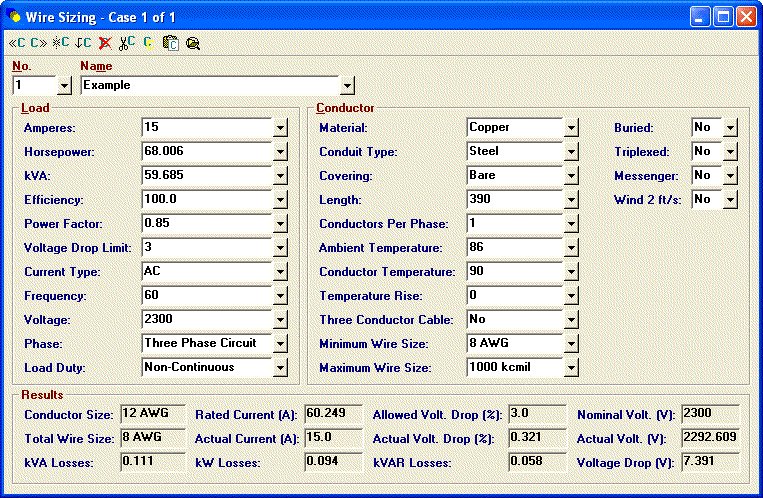
Installation calculations ensure a system perform’s appropriately.

INSTALLATION CALCULATIONS

Make sure you installation team are experienced in off-grid solar.

SOLAR SYSTEMS -WHAT KIND DO YOU NEED?

If you’re seriously considering busting your electricity bills by harvesting the sun’s energy from your rooftop, there are 2 main decisions you need to make when choosing a solar power system.

1) What configuration of solar panel system do you require?

You can choose from:

a) Grid Connect Systems

Block diagram of an on grid solar system

98% of solar systems sold in Australia are connected to the grid. The main reason being that they are the most reliable and cheapest way to add solar power to your home. Why? Because the grid acts like a giant battery with an almost infinite capacity to both provide power when you need it and to absorb excess electricity when your panels are producing more energy than your home can use. This means you don’t have to buy expensive battery systems or any fancy controllers to charge and discharge them. Most of the info on this site is related to grid connect solar power systems.

b) Off Grid Systems

Block diagram of an off grid solar system

These are expensive. You generally only go for off grid solar power if you are in one of 2 situations:

i) you live in the sticks and have no local grid connection.

ii) You have access to the grid, but you hate the thought of depending on it so much that you are happy to spend tens of thousands of dollars extra for an off grid system.

If you suspect that off grid solar power is what you need then you may enjoy my guide to Off Grid Solar Systems.

c) Hybrid Systems

Block diagram of a hybrid solar system

The “third way” which is kind of a mash up of on-grid and off-grid technologies is often called a hybrid solar power system. It is essentially a grid-connected solar power system with battery storage. It is a lot more flexible than a grid connect system, but cheaper than an off grid system.

Hybrid solar systems can be an elegant way to beat stingy feed in tariffs now operating in most Australian states where you may get as little as 8c per kilowatt-hour for the electricity you export, and have to pay more than 30c to buy it back later.

If you’d like to know how you can use hybrid systems to maximise the value of your solar electricity, and stick it to the greedy power companies, then I’ve written about hybrid solar systems here  (including how much they cost).

2) What

size solar system do you need?

Once you’ve decided on the configuration, the next most important consideration is what size solar power system do you need.

Here are the most common system sizes on the market. The following solar system sizes probably account for at least 90% of those sold in Australia:

Used to be popular – now too small to bother with: The 1.5kW Solar System (6 x 250W panels)

This size makes up a significant chunk of all systems that have ever been sold in Australia. Why? Because the pre-2013 solar rebate maxed out at 1.5kW. This means that for the previous 4 years a 1.5kW solar PV array gave you the most kW per dollar spent. Since the solar power rebate changed on Jan 1 2013, the rebate does not favour 1.5kW systems anymore. You get the same rebate for every kW bought. And that’s a good thing. Because, unless you have a super energy-efficient home, a 1.5kW system isn’t going to make much of a dent in your electricity bill. Current pricing for a good 1.5kW setup is about $2,400 – $3,400 after rebates. But you’ll struggle to find an installer that sells such small systems these days.

These days the smallest system you can easily buy is a 3kW solar power system (approx 9 x 330W panels). This will usually offset three-quarters of an average Aussie homes’ electricity usage and cost about $4,000 – $4,500. As you can see, there’s very little difference in pricing compared to a 1.5kW system considering the extra capacity you get.

If wiping out your electricity bill is important to you then skip the 5kW solar system and go for at least a 6kW system, actually, 6.6kW – I explain why here.

The next size up in the residential market would be a 10kW solar system; which has a whopping 30 solar panels (at 330W each). This size tends to be popular with large consumers that really want to crank out the green energy!

If you have a 3 phase supply, popular sizes are 15 kW all the way up to 30 kW if you have a roof the size of a football pitch.

So that’s a very quick guide to the two main choices you have to make when buying a solar power system:

1) What type? On Grid / Off Grid / Hybrid

2) What size?

A grid connect system of 6.6 kW will suit most Australian households. Big energy users should consider going even bigger. Deciding that you need grid connect is the easy bit. Choosing the correct size: 6.6 kW or bigger is where it can get tricky. Get it right and you have a great investment and almost no power bills. I get emails from people every day that have got the right advice and are ecstatic at not having electricity bills anymore.

Get the size wrong and you suffer one of two ways. You either have an array that makes almost no dent in your power bills without a costly solar upgrade, or you pay way too much for too big a system that will take a long time to pay for itself.

A good solar salesperson will only deal in solar power facts and will want to sell you the system size that makes sense for you given your energy requirements and situation. A bad one will simply pluck numbers out of the air and try to get you to go as big as possible to fatten his commission.

A good solar power salesperson will not recommend a system size until it’s been established both how much electricity you use every day and just as critically what times of day you use the electricity. Armed with that information the salesperson should be able give you an accurate estimate of your energy bill reduction and your payback period. And he/she should be prepared to guarantee it in writing!

If you want a quick explanation of why solar system sizing seems more complicated than it should be (and why a good installer who can work it out for you is a wonderful thing), then I go into great detail

INSTALLATION OF HYBRID INVERTER DEYE


Mode 3 smart load

INSTALLATION OF HYBRID INVERTER DEYE – PAGE 1

Applicable for models SUN-5K/6K/8K/10K/12K-SG04LP3-EU

About This Manual

The manual mainly describes the product information, guidelines for installation, operation and maintenance. The manual cannot include complete information about the photovoltaic (PV) system.

How to Use This Manual

Read the manual and other related documents before performing any operation on the inverter. Documents must be stored carefully and be available at all times.
Contents may be periodically updated or revised due to product development. The information in this manual is subject to change without notice. The latest manual can be acquired

1. Safety Introductions

This chapter contains important safety and operating instructions. Read and keep this manual
for future reference.

  • Before using the inverter, please read the instructions and warning signs of the battery and the corresponding sections in the instruction manual.
  • Do not disassemble the inverter. If you need maintenance or repair, take it to a professional service center.
  • Improper reassembly may result in electric shock or fire.
  • To reduce the risk of electric shock, disconnect all wires before attempting any maintenance or cleaning. Turning off the unit will not reduce this risk.
  • Caution: Only qualified personnel can install this device with a battery.
  • Never charge a frozen battery.
  • For optimum operation of this inverter, please follow the required specification to select the appropriate cable size. It is very important to correctly operate this inverter.
  • Be very cautious when working with metal tools on or around batteries. Dropping a tool may cause a spark or short circuit in batteries or other electrical parts, even causing an explosion.
  • Please strictly follow the installation procedure when you want to disconnect AC or DC terminals.
  • Please refer to the “Installation” section of this manual for the details.
  • Grounding instructions – this inverter should be connected to a permanent grounded wiring system. Be sure to comply with local requirements and regulations to install this inverter.
  • Never cause AC output and DC input to short-circuit. Do not connect to the mains when DC input short circuits.

2. Product Introduction

This is a multifunctional inverter, combining the functions of an inverter, solar charger and battery charger to offer uninterruptible power support with a portable size. Its comprehensive LCD display offers user-configurable and easily accessible button operations such as battery charging, AC/solar charging, and acceptable input voltage based on different applications.

2.1. Product Overview

SUN-5K6K8K10K12K-SG04LP3-EU
* for some hardware versions, the circuit breaker of Grid is not existed (13)
SUN-5K6K8K10K12K-SG04LP3-EU
  1. Inverter indicators
  2. LCD display
  3. Function buttons
  4. Power on/off button
  5. DC switch
  6. Parallel port
  7. Meter-485 port
  8. Battery input connectors
  9. Function port
  10. Mode BUS port
  11. BMS port
  12. PV input with two MPPT
  13. *Circuit breaker of Grid
  14. Load
  15. Generator input
  16. WiFi Interface

2.2. Product Size

SUN-5K6K8K10K12K-SG04LP3-EU size
Inverter Size
SUN-5K6K8K10K12K-SG04LP3-EU size
Inverter Size
Mounting bracket size for SUN-5K6K8K10K12K-SG04LP3-EU
Mounting bracket sizes

2.3. Product Features

  • 230V/4OOV Three phase Pure sine wave inverter.
  • Self-consumption and feed-in to the grid.
  • Auto restart while AC is recovering.
  • Programmable supply priority for battery or grid.
  • Programmable multiple operation modes: On grid, off grid and UPS.
  • Configurable battery charging current/voltage based on applications by LCD setting.
  • Configurable AC/Solar/Generator Charger priority by LCD setting.
  • Compatible with mains voltage or generator power.
  • Overload/over temperature/short circuit protection.
  • Smart battery charger design for optimized battery performance
  • With limit function, prevent excess power overflow to the grid.
  • Supporting WIFI monitoring and build-in 2 strings for 1 MPP tracker, 1 string for 1 MPP tracker.
  • Smart settable three stages MPPT charging for optimized battery performance.
  • Time of use function.
  • Smart Load Function.

2.4. Basic System Architecture

The following illustration shows the basic application of this inverter.
It also includes the following devices to have a Complete running system.
– Generator or Utility
– PV modules

Consult with your system integrator for other possible system architectures depending on your requirements.

This inverter can power all kinds of appliances in a home or office environment, including motor-type appliances such as refrigerators and air conditioners.

SUN-29.930354050K-SG01HP3-EU-BM234 29.9-50kW Three Phase 234 MPPT Hybrid Inverter High Voltage Battery

3. Installation

3.1. Parts List (12)

SUN-5K6K8K10K12K-SG04LP3-EU size
Hybrid Inverter x1
Mounting bracket size for SUN-5K6K8K10K12K-SG04LP3-EU
Wall mounting bracket x1
Installation of Hybrid Inverter DEYE - Page 1
Stainless steel anti-collision-bolt M8x8Ox4
Installation of Hybrid Inverter DEYE - Page 1
Parallel communication cable x1
L-type Hexagon wrench x1
Battery temperature sensor x1
User manual x1
User manual x1
Wi-Fi-Plug (optional) x1
Meter (optional) x 1
Sensor Clamp x 3
Sensor Clamp x 3
DC+DC- Plug connectors including metal terminal xN
Sensor DC+DC- Plug connectors including metal terminal xN

3.2. Mounting instructions

Installation Precaution

This Hybrid inverter is designed for outdoor use(lP65), Please make sure the installation site meets the below conditions:

  • Not in direct sunlight
  • Not in areas where highly flammable materials are stored.
  • Not in potentially explosive areas.
  • Not in the cool air directly.
  • Not near the television Antenna or antenna cable.
  • Not higher than the altitude of about 2000 meters above sea level.
  • Not in an environment of precipitation or humidity (>95%)

Please AVOID direct sunlight, rain exposure, and snow laying up during installation and operation. Before connecting all wires, please take off the metal cover by removing
the screws as shown below:

SUN-5K6K8K10K12K-SG04LP3-EU

Considering the following points before selecting where to install:

  • Please select a vertical wall with load-bearing capacity for installation, suitable for installation on concrete or other non-flammable surfaces, installation is shown below.
  • Install this inverter at eye level in order to allow the LCD display to be read at all times.
  • The ambient temperature is recommended to be between -40~60“C to ensure optimal operation.
  • Be sure to keep other objects and surfaces as shown in the diagram to guarantee sufficient heat dissipation and have enough space for removing wires.
Installation of Hybrid Inverter DEYE - Page 1

For proper air circulation to dissipate heat, allow a clearance of approx. 50cm to the side and approx. 50cm above and below the unit. And 100cm to the front.

Mounting the inverter

Remember that this inverter is heavy! Please be careful when lifting out from the package. Choose the recommended drill head (as shown below pic) to drill 4 holes on the wall, 82-90mm deep.

  1. Use a proper hammer to fit the expansion bolt into the holes.
  2. Carry the inverter and hold it, make sure the hanger aims at the expansion bolt, and fix the inverter on the wall.
  3. Fasten the screw head of the expansion bolt to finish the mounting.
Inverter hanging plate installation

3.3 Battery connection

For safe operation and compliance, a separate DC over-current protector or disconnect device is required between the battery and the inverter. In some applications, switching devices may not be required but over-current protectors are still required. Refer to the typical amperage in the table below for the required fuse or circuit breaker size.

Model Wire Size Cablel (mm2) Torque value (max)
5 Kw 2 AWG 35 24.5 Nm
6/8 Kw 1 AWG 50 24.5 Nm
10/12 Kw 1/0 AWG 50 24.5 Nm
Chart 3-2 Cable size

All wiring must be performed by a professional person

Please follow the below steps to implement battery connection:

  1. Please choose a suitable battery cable with the correct connector which can well fit into the battery terminals.
  2. Use a suitable screwdriver to unscrew the bolts and fit the battery connectors in, then fasten the bolt by the screwdriver, making sure the bolts are tightened with a torque of 24.5 N.M in a clockwise direction.
  3. Make sure the polarity at both the battery and inverter is correctly connected.
Install SUN-5K6K8K10K12K-SG04LP3-EU
For the 5-12KW model, the battery connector screw size: M10
DC Battery Input 2/1AWG Wire Size
  1. In case of children touch or insects go into the inverter, Please make sure the inverter connector is fastened to a waterproof position by twisting it clockwise.

Installation must be performed with care.

Before making the final DC connection or closing DC breaker/disconnect, be sure positive(+) must be connected to positive(+) and negative(-) must be connected to negative(-). A reverse polarity connection on the battery will damage the inverter.

3.3.2 Function port definition

Inverter-Install

A

CN1:

  • TEMP (1,2): battery temperature sensor for the lead acid battery.
  • CT-L1 (3,4): current transformer (CT1) for “zero export to CT” mode clamps on L1 when in a three-phase system.
  • CT-L2 (5,6): current transformer (CT2) for “zero export to CT” mode clamps on L2 when in a three-phase system.
  • CT-L3 (7,8): current transformer (CT3) for “zero export to CT” mode clamps on L3 when in a three-phase system.

CN2:

  • G-start (1,2): dry contact signal for the startup of the diesel generator. When the “GEN signal” is active, the open contact (GS) will switch on (no voltage output).
  • G-valve (3,4): Dry contact output. When the inverter is in off-grid mode and the ”signal island mode” is checked, the dry contact will switch on.
  • Grid_Ry (5,6): reserved.
  • RSD (7,8): When the battery is connected and the inverter is in “ON” status, it will provide 12Vdc.
Inverter-Install Switching

B

  • Parallel A: Parallel communication port 1 (CAN interface)
  • Parallel B: Parallel communication port 2 (CAN interface)
  • Meter_485: for energy meter communication.
  • ModeBUS: Reserved.
  • BMS: BMS port for battery communication(CAN/RS48).

3.3.3 Temperature sensor connection for lead-acid battery

Inverter

3.4 Grid connection and backup load connection

  • Before connecting to the grid, please install a separate AC breaker between the inverter and the grid. Also, it is recommended that installs an AC breaker between the backup load and inverter. This will ensure the inverter can be securely disconnected during maintenance and fully protected from overcurrent. The recommended of AC breaker for the load port is 20A for 8kw, 32A for 10kw, and 32A for 12KW. The recommended of AC breaker for the grid port is 63A for 8kw, 63A for 10kw, and 63A for 12KW.
  • There are three terminal blocks with “Grid” “Load” and “GEN” markings. Please do not misconnect in ut and output connectors.
Model Wire Size Cablel (mm2) Torque value (max)
5/6/8/12 Kw 10 AWG 4 1.2 Nm
Backup load connection
Model Wire Size Cablel (mm2) Torque value (max)
5/6/8/12 Kw 10 AWG 6 1.2 Nm
Grid connection – Chart 3-3 Recommended Size for AC wires

Please follow the below steps to implement Grid, load and Gen port connection:

  1. Before making the Grid, load and Gen port connection, be sure to turn off the AC breaker or disconnector first.
  2. Remove the insulation sleeve 10 mm in length, unscrew the bolts, insert the wires according to the polarities indicated on the terminal block, and tighten the terminal screws. Make sure the connection is complete.
Grid, load and Gen port connection of Inverter

Be sure that the AC power source is disconnected before attempting to wire it to the unit.

  1. Then, insert AC output wires according to the polarities indicated on the terminal block and tighten the terminal. Be sure to connect corresponding N wires and PE wires to related terminals as well.
  2. Make sure the wires are securely connected.
  3. Appliances such as air conditioner are required at least 2-3 minutes to restart because it is
  4. required to have enough time to balance refrigerant gas inside the circuit. If a power shortage occurs and recovers in a short time, it will cause damage to your connected appliances. To prevent this kind of damage, please check with the manufacturer of the air conditioner if it is equipped with a time-delay function before installation. Otherwise, this inverter will trigger an overload fault and cut off output to protect your appliance but sometimes it still causes internal damage to the air conditioner.

3.5 PV Connection

Before connecting to PV modules, please install a separate DC circuit breaker between the inverter and PV modules. It is very important for system safety and efficient operation to use appropriate cable for PV module connection. To reduce the risk of injury, please use the proper recommended cable size as below.

Model Wire Size Cablel (mm2)
5/6/8/12 Kw 12 AWG 4
Chart 3-4 Cable size

To avoid any malfunction, do not connect any PV modules with possible current leakage to the inverter. For example, grounded PV modules will cause current leakage to the inverter. When using PV modules, please ensure the PV+ & PVof solar panel is not connected to the system ground bar.

It is requested to use the Pv junction box with surge protection. Otherwise, it will cause damage to the inverter when lightning occurs on PV modules.

3.5.1 PV Module Selection:

When selecting proper PV modules, please be sure to consider below parameters:

  1. Open circuit Voltage (Voc) of PV modules does not exceed the max. PV array open circuit voltage of the inverter.
  2. Open circuit Voltage (Voc) of PV modules should be higher than min. start voltage.
  3. The PV modules used to connect to this inverter shall be Class A rating certified according to IEC 61730.
Inverter Model 5 Kw 6 Kw 8 Kw 10 Kw 12 Kw
PV Input Voltage 550V (160V ~ 800V) 550V (160V ~ 800V) 550V (160V ~ 800V) 550V (160V ~ 800V) 550V (160V ~ 800V)
PV Array MPPT Voltage Range 200V ~ 650V 200V ~ 650V 200V ~ 650V 200V ~ 650V 200V ~ 650V
No. of MPP Trackers 2 2 2 2 2
No. of Strings per MPP Tracker 1+1 1+1 1+1 2+1 2+1
Chart 3-5

3.5.2 PV Module Wire Connection:

  1. Switch the Grid Supply Main Switch(AC)OFF.
  2. Switch the DC isolator OFF.
  3. Assemble the PV input connector to the inverter.

Safety Hint:
When using PV modules, please ensure the PV+ & PV- of the solar panel are not connected to the system ground bar.

Safety Hint:
Before connection, please make sure the polarity of the output voltage of PV array matches the “DC+” and “DC-” symbols.

Safety Hint:
Before connecting the inverter, please make sure the PV array open circuit voltage is within 1000V of the inverter.

Pic 5.1 DC+ male connector
Pic 5.2 DC- female connector

Safety Hint:
Please use an approved DC cable for the PV system.

Cable type Cross section (mmz)
Industry generic PV cable 4.0”6.0 (model: PV1-F) Range Recommended value
4.0”6.0
(12~10AWG)
4.0 (12AWG)

Chart 3-6The steps to assemble the DC connectors are listed as follows:
a) Strip off the DC wire about 7mm, and disassemble the connector cap nut (see picture 5.3)

Pic 5.3 Disassemble the connector cap nut

b) Crimping metal terminals with crimping pliers as shown in picture 5.4.

Pic 5.4 Crimp the contact pin to the wire

c) Insert the contact pin to the top part of the connector and screw up the cap nut to the top part of the connector. (as shown in picture 5.5)

Pic 5.5 connector with cap nut screwed on

d) Finally insert the DC connector into the positive and negative input of the inverter, like shown in picture 5.6

Pic 5.6 DC input connection

Warning:
Sunlight shines on the panel will generate voltage, high voltage in series may cause danger to life. Therefore, before connecting the DC input line, the solar panel needs to be blocked by the opaque material and the DC switch should be ‘OFF’, otherwise, the high voltage of the inverter may lead to life-threatening conditions.

Warning:
Please use its own DC power connector from the inverter accessories. Do not interconnect the connectors of different manufacturers.Max. DC input current should be 20A. if exceeds, it may damage the inverter and it is not covered by Deye warranty.

3.6 CT Connection

CT Connection

*Note: when the reading of the load power on the LCD is not correct, please reverse the CT arrow.

3.6.1 Meter Connection

Meter Connection
Meter Connection

Note:
When the inverter is in the off-grid state, the N line needs to be connected to the earth.

Note:
In the final installation, the breaker certified according to IEC60947-1 and IEC 60947-2 shall be installed with the equipment.

3.7 Earth Connection (mandatory)

Ground cable shall be connected to the ground plate on the grid side this prevents electric shock if the original protective conductor fails.

Earth Connection (mandatory)

3.8 WIFI Connection

For the configuration of the Wi-Fi Plug, please refer to the illustrations of the Wi-Fi Plug. The Wi-Fi Plug is not a standard configuration, it’s optional.

3.9 Wiring System for Inverter

This diagram is an example of an application that neutral connects with the PE in a distribution box.
For countries such as Australia, New Zealand, South Africa, etc., please follow local wiring regulations!

Wiring System for Inverter

3.10 Wiring diagram

This diagram is an example of an application in which neutral is separated from the PE in the distribution box/ For countries such as China, Germany, the Czech Republic, Italy, etc., please follow local wiring regulations!
Note: The backup function is optional in the German market. Please leave the backup side empty if the backup function is not available in the inverter.

Wiring diagram
Installation of Hybrid Inverter DEYE - Page 1

1) DC Breaker for battery
SUN 5K—SG—EU: 150A DC breaker
SUN 6K—SG—EU: 200A DC breaker Backup Load
SUN 8K—SG—EU: 250A DC breaker
SUN 10K—SG—EU: 300A DC breaker
SUN 12K—SG—EU: 300A DC breaker
2) AC Breaker for backup load
SUN SK—SG—EU: 16A AC breaker
SUN 6K—SG—EU: 16A AC breaker
SUN 8K—SG—EU: 20A AC breaker
SUN 10K—SG—EU: 32A AC breaker
SUN 12K—SG—EU: 32A AC breaker
3) AC Breaker for grid
SUN 5K—SG—EU: 63A AC breaker
SUN 6K—SG—EU: 63A AC breaker
SUN 8K—SG—EU: 63A AC breaker
SUN 10K—SG—EU: 63A AC breaker
SUN 12K—SG—EU: 63A AC breaker
4) AC Breaker for home load
Depends on the household loads

3.11 Typical application diagram of diesel generator

Max. 10pcs parallel for on-grid and off-grid operation.

Installation of Hybrid Inverter DEYE - Page 1

4. OPERATION

4.1 Power ON/OFF

Once the unit has been properly installed and the batteries are connected well, simply press the On/Off button (located on the left side of the case) to turn on the unit. When the system is without a battery connected, but connected with either PV or grid, and the ON/OFF button is switched off, LCD will still light up (Display will show OFF), In this condition, when switching on the ON/OFF button and selecting NO battery, the system can still work.

4.2 Operation and Display Panel

The operation and display panel, shown in the below chart, is on the front panel of the inverter. It includes four indicators, four function keys, and an LCD display, indicating the operating status and input/output power information.

LED Indicator Messages
DC Green-led solid light PV Connection normal
AC Green-led solid light Grid Connection normal
Normal Green-led solid light Inverter operating normally
Alarm Red-led solid light Malfunction or warning
Chart 4-1 LED indicators
Function Key Description
Esc To exit the setting mode
Up To go to the previous selection
Down To go to the next selection
Enter To confirm the selection


How to Install a Solar Water Pump Step-by-Step Guide

In the pursuit of sustainable and cost-effective water pumping solutions, transitioning to solar-powered water pumps stands out as an environmentally conscious choice. We will be going through the step-by-step installation process for solar water pumps in a detailed manner. We shall also look into the common questions regarding installation and maintenance as well.

When it comes installing a Solar Water Pump, it consist of a 4 step process, lets look into it one by one

Step 1: Site Selection and Sun Exposure

Choose a location that receives maximum sunlight exposure throughout the day. Confirm that the site allows for proper orientation and angle adjustment of the solar panels to capture the most sunlight. Proper sun exposure is very much important for the efficiency of the entire solar water pump system.

Step 2: Proper Sizing of the Solar Water Pump System

  1. Determine Water Requirements: Identify the specific water needs of your application, whether it’s for irrigation, domestic use, or other purposes. Accurately calculate the volume of water required to ensure the solar water pump system is appropriately sized.
  2. Match Solar Panel Capacity: Align the solar panel capacity with the power requirements of the pump. This matching ensures that the system operates efficiently, harnessing sufficient solar energy to power the pump effectively.

Step 3: Quality Components and Professional Installation

  1. Invest in High-Quality Components: Choose reliable and durable components for your solar water pump system, including the pump itself, solar panels, controller, and any additional accessories. High-quality components contribute to the system’s long lasting performance
  2. Consider Professional Installation: If you are not familiar with electrical and plumbing work, it is advisable to hire a professional installer, who could set the system correction and reduce the risk of error or malfunctions

Step 4: Battery Storage for Continuous Operation

  1. Assess System Design: Determine if your solar water pump system is intended for intermittent or emergency use. If so, consider integrating a battery storage system to ensure continuous operation during periods of low sunlight or power outages.
  2. Properly Size and Configure Battery Bank: Ensure that the battery bank is appropriately sized to meet the pump’s power requirements. Upon installation ensure the batter system can provide necessary back up

Can I Install a Solar Water Pump Directly to the Solar Panel?

Connecting a solar water pump directly to the solar panel is not advisable. Atlthough it may seem convenient, but it can lead to issues and may affect the lifespan of the Solar

Solar pump. Its is best to use a control unit.

Here’s why:

  1. Voltage Regulation: Solar panels generate varying voltages based on sunlight intensity. Connecting the pump directly to the solar panel without regulation can expose the pump to fluctuating voltage levels, potentially causing damage over time.
  2. Control Unit Functionality: A control unit regulates the power flow from the solar panels to the pump, ensuring a stable and consistent supply of energy. It protectthe pump from being overloaded or damaged due to power fluctuations.
  3. Optimal Performance: Using a control unit allows for better control and optimization of the solar water pump system. It ensures that the pump receives the right amount of power, maximizing efficiency and performance.

When installing a solar water pump, always follow the manufacturer’s guidelines and recommendations. Including a control unit in your system is a crucial step to safeguard the pump and ensure a trouble-free operation. If you are uncertain about the installation process or lack experience in electrical work, it is advisable to seek the assistance of a professional installer to guarantee a correct and secure setup.

What Are the Key Steps to Install a Solar Water Pump?

Breaking down the installation process into key steps provides a clear roadmap for those venturing into solar water pump installation. Starting with the site assessment, then moving on to component assembly, water source connection, and solar panel integration, this step-by-step approach simplifies the process. Emphasize the importance of adhering to the manufacturer’s guidelines at each stage for optimal results. ​
Installing a solar water pump involves several key steps to ensure a successful and efficient setup. Here is a comprehensive guide to walk you through the process:

1. Site Assessment:

Begin by selecting a location that receives maximum sunlight exposure throughout the day. This ensures optimal energy production for the solar panels. Confirm that the chosen site allows for proper orientation and angle adjustment of the solar panels to capture the most sunlight.

2. Water Requirement Determination:

Identify the specific water requirements for your intended application, whether it’s for irrigation, domestic use, or other purposes. Calculate the volume of water needed to determine the appropriate size for the solar water pump system.

3. Solar Panel Sizing:

Match the solar panel capacity to the power requirements of the pump. It ensures that the solar water pump system operates efficiently by using sufficient solar energy to power the pump

4. Component Assembly:

Assemble the necessary components, including the solar pump, solar panels, controller, and any additional accessories. Follow the manufacturer’s guidelines carefully during this process to ensure proper integration and functionality.

5. Water Source Connection:

Establish a water source for the pump, whether it involves digging a borewell or tapping into an existing water supply. Connect the pump to the water source, ensuring a secure and leak-free connection.

6. Solar Panel Integration:

Connect the solar panels to the solar water pump system. Verify that the panels are correctly positioned and oriented for maximum sunlight absorption. Follow the provided instructions to connect the panels to the controller and pump.

7. Control Unit Installation:

Include a control unit in your system to regulate the power flow from the solar panels to the pump. The control unit acts as a protective measure, preventing the pump from damage due to voltage irregularities and ensuring optimal performance.

8. Testing and Calibration:

Before putting the system into full operation, conduct thorough testing. Check for any leaks, confirm that the pump is working correctly, and ensure the control unit is regulating power effectively. Calibrate the system as needed to address any issues.

9. Regular Maintenance:

Implement a routine maintenance schedule to keep the solar water pump system in optimal condition. Tasks may include cleaning solar panels, checking connections, inspecting the pump, and ensuring the control unit is functioning correctly.

4. How Long Does It Take to Install a Solar Water Pump?

The duration of a solar water pump installation varies based on factors such as the installer’s experience, site conditions, and system complexity. On average, a professional installer may complete the setup in one to two days. This timeframe underscores the efficiency and relatively quick implementation of solar water pump systems. ​

The duration of installing a solar water pump can vary based on several factors, including the complexity of the system, the installer’s experience, site conditions, and the specific requirements of the installation. On average, a professional installer can complete the installation process within one to two days.

Here is a breakdown of the factors influencing the installation timeline:

  1. System Complexity: The complexity of the solar water pump system, including the number of components, the need for additional accessories, and the sophistication of the control unit, can impact the installation time.
  2. Installer Experience: The expertise and experience of the installer play a significant role. A seasoned professional with prior experience in solar water pump installations is likely to complete the process more efficiently than someone with less experience.
  3. Site Conditions: The characteristics of the installation site, such as accessibility, terrain, and proximity to the water source, can affect the installation timeline. Sites with challenging conditions may require more time for proper setup.
  4. Preparedness and Planning: Adequate preparation, including having all necessary components on hand and a well-thought-out installation plan, can contribute to a faster and smoother installation process.
  5. Size of the System: The size and capacity of the solar water pump system also factor into the installation time. Larger systems may involve more components and connections, requiring additional time for assembly and configuration.

How to Install Solar Water Pump with Battery?

Solar water pumps are specially designed to utilize DC electricity from solar panels. The pumps must work during low light conditions, when power is reduced, without stalling or overheating. Low volume pumps use positive displacement (volumetric) mechanisms which seal water in cavities and force it upward. The submersible pump can realize working at sunrise and resting at sunset, no need any person look after it, no need diesel, no need power grid, and can be used with irrigation equipments to save water, energy and cost.

So, today we will talk about how to install a solar water pump with battery.

Wiring

  1. Connecting the power cable of the motor to the W, V and U terminals.
  2. Conneting the DC power supply to P+, P-, (battery or solar panel).

Wiring diagram of solar water pump

How to install the solar water pump with battery?

  1. We using a 48VDC battery, connecting the connector to the solar water pump outlet. If the pump will be put in deep water, it shold be lifted by ropes. (Becareful not to use the power cable to lift pump).
  2. Putting the pump into the water. When in pond/ pool/ river/ lake, the water inlet of the pump must below the water level.
  3. When the solar pump is putting into a narrow deep well, the water inlet of the pump should be 7-8 meters lowers than the water level so that the pump can pump enough water. The controller automatically recognizes that the pump is connected the battery or solar panel.
  4. Then press”ON”, the controller starts to work.
  5. Press “switch” to view the current speed. The outlet bagan to spray water.
  6. Press ▼ to decrease the motor speed. (When the power supply is battery.)
  7. Press “Enter” to confirm the setting. Then the water discharge is obviously reduced. The mimimum speed that canbe set is 1000 rpm.
  8. Switching to check the current is 0.7A, power is 38W, and voltage is 49.9V.
  9. Press the “OFF” to stop pumping. (When the power supply is solar penel, the pump will automatically start or stop).
  10. Connect the level snesor according to the wiring diagram. It is often used in water tanks. The level sensor is onnected to the TH and COM terminals.How to install solar water pump with battery

When the float switch is lifted by water, the pump stops working. The TANK indicator light on the controller panel is always on. After 30 minutes, the solar water pump will automatically restart and pump water.

If you want to know more details about the installing

 solar water pump with battery, please check the video below.

OFF GRID SOLAR SYSTEM INSTALLATION GUIDE


DIY OFF GRID SOLAR SYSTEM

Day by day the price of the solar panel falls gradually. But still, installation of a complete off-grid solar system is costly. So I write this instructable to get all the components of your solar system separately and assemble it all by yourself.

install a solar panel system to cover your home power needs. This tutorial is for you.

I have tried my best to guide you step by step from buying different components to wiring everything by yourself.

Only you have to know some basic electrical and math for designing the entire system. Instead of this, I have attached links of my other Instructables to make the charge controller and energy meter.

For an off-grid solar system, you need four basic components

1. Solar Panel (PV Panel)

2.Charge Controller

3. Inverter

4.Battery

Besides the above components you need a few more things like Copper Wire, MC4 Connector, breaker, meter, and fuses, etc.

In the next few steps, I will explain in details how you can choose the above components according to your requirement.

Note: In the picture I have shown a big solar panel of 255W @ 24V, two batteries of 12V @ 100Ah each, 30A @ 12/24V PWM solar charge controller and a 1600 VA pure sine wave inverter. But during the calculation, I have taken a smaller solar system example for better understanding.

STEP 1: CALCULATE YOUR LOAD

Before choosing the components you have to calculate what is your load, how much time it will run etc. If anyone knows basic maths then It is very simple to calculate.

1. Decide what appliances (light, fan, tv, etc ) you want to run and how much time (hour).

2. See the specification chart in your appliances for power rating.

3. Calculate the Watt Hour which is equal to the product of power rating of your appliances and time ( hr) of the run.

Example :

Lets you want to run an 11W CFL for 5hour from the solar panel, then the watt-hour is equal to

Watt Hour = 11W x 5 hr = 55

4. Calculate the total Watt Hour: Just like a CFL calculate the watt-hour for all the appliances and add them together.

Example :

CFL =11W x 5 hr = 55

Fan = 50 W x 3hr = 150

TV = 80W x 2hr = 160

————————————————

Total Watt Hour = 55+150+160 = 365

Considering 30% energy lost in the system.

So total Watt Hour per day = 365 x 1.3 = 474.5 Wh which can be round off to 475 Wh

Now the load calculation is over. The next thing is to choose the right components to match your load requirement.

If you are not interested to do the above maths then use a load calculator for this calculation. You can use this nice

STEP 2: SOLAR PANEL SELECTION

Loading video

The Solar Panel converts the sunlight into electricity as direct current (DC). These are typically categorized as

monocrystalline or polycrystalline. Monocrystalline is costlier and efficient than the polycrystalline panel.

Solar panels are generally rated under standard test conditions (STC): irradiance of 1,000 W/m², the solar spectrum of AM 1.5 and module temperature at 25°C.

RATING OF SOLAR PANEL :

The solar panel size should be selected in such a way that it will charge the battery fully during the one day time.

During the 12hr day time, the sunlight is not uniform it also differs according to your location around the globe. So we can assume 4 hours of effective sunlight which will generate the rated power.

Total Wp of PV panel capacity needed = 475Wh /4 = 118.75 W

By taking some margin you can choose a 120 Watt, 12v solar panel.

Here you should not confuse with the 12V. I wrote 12V as it is suitable for charging the 12V battery. But actually the Solar panel voltage is around 17V or more.

STEP 3: BATTERY SELECTION

Loading video

The output from the solar panel is dc power. This power is generated during day time only. So if you want to run a dc load during day time then it seems to be very easy. But doing this is not a good decision because.

A solar charge controller is a device that is placed between a solar panel and a battery. It regulates the voltage and current coming from your solar panels. It is used to maintain the proper charging voltage on the batteries. As the input voltage from the solar panel rises, the charge controller regulates the charge to the batteries preventing any overcharging.

1. Square Wave

2. Modified Sine Wave

3. Pure Sine Wave

Square wave inverter is cheaper among the all but not suitable for all appliances. Modified Sine Wave output is also not suitable for certain appliances, particularly those with capacitive and electromagnetic devices such as a fridge, microwave oven and most kinds of motors. Typically modified sine wave inverters work at lower efficiency than pure sine wave inverters.

So as per my opinion choose a pure sine wave inverter.

It may be grid-tied or stand-alone. In our case, it is obviously stand alone.

RATING OF INVERTER :

The power rating should be equal or more than the total load in watt at any instant.

In our case the maximum load at any instant = Tv (50W) +Fan (80W) +CFL (11W) =141W

By taking some margin we can choose a 200W inverter.

As our system is 12 v we have to select a 12V DC to 230V/50Hz or 110V/60Hz AC pure sine wave inverter.

Note :

Appliances like fridge, hair drier, vacuum cleaner, washing machine, etc likely to have their starting power consumption several times greater than their normal working power (typically this is caused by electric motors or capacitors in such appliances). This should be taken into account when choosing the right size of the inverter.

STEP 6: SERIES AND PARALLEL CONNECTION

After calculating the battery capacity and solar panel rating you have to wire them. In many cases, the calculated solar panel size or battery is not readily available in the form of a single unit in the market. So you have to add a small solar panel or batteries to match your system requirement. To match the required voltage and current rating we have to use series and parallel connection.

1. Series Connection :

To wire any device in series you must connect the positive terminal of one device to the negative terminal of the next device. The device in our case may be a solar panel or battery.

In series connection the individual voltages of each device are additive.

Example :

lets 4 12V batteries are connected in series, then the combination will produce 12 + 12 + 12 + 12 = 48 volts.

In a series combination, the current or amperage is the same.

So if these devices were batteries and each battery had a rating of 12 Volts and 100 Ah then the total value of this series circuit would be 48 Volt, 100Ah. If they were solar panels and each solar panel had a rating of 17 volts(Osc voltage) and were rated at 5 amps each then the total circuit value would be 68 volts, 5 amps.

2. Parallel Connection :

In a parallel connection, you must connect the positive terminal of the first device to the positive terminal of the next device and negative terminal of the first device to the negative terminal of the next device.

In a parallel connection, the voltage remains the same but the current rating of the circuit is a sum of all the devices.

Example :

Lets two batteries of 12v,100Ah are connected in parallel then the system voltage remains 12 volts but the current rating is 100+100=200Ah. Similarly, if two solar panels of 17V and 5 amps are connected in parallel then the system will produce 17 Volts, 10 amps.

STEP 7: WIRING

The first component we are going to wire is the Charge Controller. At the bottom of the Charge Controller, there are 3 signs in my charge controller. The first one from the left is for the connection of the Solar Panel having positive (+) and negative (-) sign. The second one with plus (+) and minus (-) sign is for the Battery connection and the last one for the direct DC load connection like DC lights.

As per the charge controller manual always connect the Charge Controller to the Battery first because this allows the Charge Controller to get calibrated to whether it is 12V or 24V system. Connect the red (+) and black (-) wire from the battery bank to the charge controller.

Note: First connect the black /negative wire from the battery to the charge controller’s negative terminal, then connect the positive wire.

After connecting the battery with charge controller you can see the Charge Controller indicator led lights up to indicate the Battery level.

After connecting this inverter terminal for battery charging is connected to corresponding positive and negative terminals of the battery.

Now you have to connect the solar panel to the charge controller. At the backside of the Solar Panel, there is a small junction box with 2 connected wires with positive(+) and negative (-) sign. The terminal wires are normally smaller in length. To connect the wire to the charge controller you need a special type connector which is commonly known as MC4 connector. See the picture. After connecting the solar panel to the charge controller the green led indicator will light if sunlight is present.

Note: Always connect the Solar Panel to Charge Controller while facing the Panel away from the sun or you may cover the panel with a dark material to avoid sudden high voltage coming from the solar panel to the Charge Controller which may damage it.

SAFETY :

It is important to note that we are dealing with the DC current. So the positive (+) is to be connected to positive (+) and negative (-) with negative (-) from Solar Panel to Charge Controller. If it gets mixed up, the equipment can go burst and may catch fire. So you need to be extremely careful when connecting these wires. It is recommended to use 2 color wires i.e. red and black color for positive (+) and negative (-). If you don’t have a red and black wire you may wrap red and black tap at the terminals.

Connect the dc load or dc light at last.

Additional Protection :

Though charge controller and inverter have inbuilt fuses for protection, you can put switches and fuses in the following places for additional protection and isolation.

1. In between solar panel and charge controller

2. In between the charge controller and battery bank

3. In between battery and inverter

Metering and Data logging :

If you are interested to know how much energy is produced by your solar panel or how much energy is consumed by the appliances you have to use energy meters.

Besides this, you can monitor the different parameters in your off-grid solar system by remote data logging

For DIY based energy meter you can see my instructable on ENERGY METER which has both metering and data logging capability.

After wiring everything the off-grid Solar system is ready for use.

STEP 8: SELECTING THE SOLAR CABLE


The current generated from the solar panels should reach the Battery with minimum loss. Each cable has its own ohmic resistance. The voltage drop due to this resistance is according to Ohm’s law

V = I x R (Here V is the voltage drop across the cable, R is the resistance and I is the current).

The resistance ( R ) of the cable depends on three parameters:

1.Cable Length: Longer the cable, more is the resistance

2. Cable Cross-section Area: Larger the area, smaller is the resistance

3. The material used: Copper or Aluminum. Copper has lesser resistance compared to Aluminium

In this application, copper cable is preferable.

You need to enter the following parameters :

1. Solar Panel Operating Voltage (Vmp)

2. Solar Panel Operating Current (Imp)

3. Cable Length from Solar Panel to Battery

4. The expected loss in percentage

The first two parameters ( Vmp and Imp) can be easily found from the specification sheet on the backside of the solar panel or from the datasheet. The cable length depends on your installation. The loss percentage considered for good design is around 2 to 3%.

In the earlier step, we have already finalized the Solar panel, the rating. From the Solar panel specification sheet Vmp = 36.7V and Imp = 6.94A ( rounded off to next higher number i.e 37V and 7A). Let the distance between the Solar panel and the Battery is 30 feet and the expected loss is 2%. By using the above values in the online calculator by RENOGY, The cable size is 12 AWG.

The calculation screenshot is also attached for reference.

You can buy the Solar cables from us

Note: The voltage grade of the cable should be matched with the Solar Panel maximum system voltage.

STEP 9: SELECTING THE CORRECT SIZE POWER INVERTER BATTERY CABLES

Updated on 17.12.2019

It is very important to be sure you are using the appropriate cable size for your inverter/battery. Failing to do so could lead to your inverter not supporting full loads and overheating, which is a potential fire hazard. Use this as a guide for choosing the proper cable size, and be sure to contact a professional electrician or our tech team with any additional questions you may have.

1. What size inverter do you have?

2. What is the DC voltage of your battery bank?

3. Now divide the inverter’s wattage by your battery voltage; this will give you the maximum current for your cables.

Example Calculation

Current (Amps ) = Power (Watts ) / Voltage (Volt)

Consider 1500 Watt inverter connected to the 24V battery bank.

(1500 W)/(24 Vdc)=62.5 A

So, 62.5 A is the maximum current that the cable needs to support in order to properly provide the current to the inverter. The next higher size available on the table is 100A.

Use the above chart as a guide to determine which size cable will be best for your application.

In our example, we can see that 2/0 AWG cable would be appropriate.

NOTE: For distances over 10 feet, the voltage drop over the cables will occur due to resistance through the wiring. If you will need to run cables longer than 10 feet, it is recommended that you increase the cable size in order to compensate for voltage loss. If you are unsure about your application feel free to give us a call and we will be able to assist you in finding the right cable.

STEP 10: MOUNTING THE SOLAR PANEL

After design the solar system. Buy all the components with an appropriate rating as per the previous steps.

Now it is time to mount the solar panel. First, choose a suitable location on the rooftop where there is no obstruction sunlight.

Prepare the mounting stand: You can make it on your own or it is better to buy one from any store. In my case, I have taken the drawing from the solar panel company and made it at a nearby welding shop. The tilt of the stand is nearly equal to the latitude angle of your location.

I made a small wooden mounting stand for my 10 Watt solar panel. I have attached the pictures so that anyone can make it easy.

Tilting: To get the most from solar panels, you need to point them in the direction that captures the maximum sunlight. Use one of these formulas to find the best angle from the horizontal at which the panel should be tilted:

>> If your latitude is below 25°, use the latitude times 0.87.

>> If your latitude is between 25° and 50°, use the latitude, times 0.76, plus 3.1 degrees.

First place the stand in such a way that the face is directed towards the south.Mark the leg position over the roof.

Then make a rough surface at each leg of the stand by using a sharp object. I made around 1Sq feet size rough surface over the roof at each leg. This is helpful for perfect bonding between the roof and concrete.

Prepare concrete mix: Take cement and stones with a 1:3 ratio then add water to make a thick mix. Pour concrete mix at each leg of the stand. I made a heap shape concrete mix to give maximum strength.

Mounts the panels to the stand:At the backsides, the solar panel has inbuilt holes for mounting. Match the solar panel holes with the stand/platform holes and screw them together.

Wire the solar panel: At the back sides of the solar panel a small junction box is there with a positive and negative sign for polarity. In a large-size solar panel, this junction box has terminal wires with MC4 connector but for small size panel, you have to connect the junction box with external wires. Always try to use red and black wire for the positive and negative terminal connection. If there is provision for earth wire the use a green wire for wiring this.

STEP 12: SOLAR PV DESIGN WORKSHEET

I found a nicely documented worksheet on Solar PV Design

This is a simple design worksheet for stand-alone solar PV systems. It explains the design process and explains some of the practicalities of building a system.