INSTALLATION OF HYBRID INVERTER DEYE


Mode 3 smart load

INSTALLATION OF HYBRID INVERTER DEYE – PAGE 1

Applicable for models SUN-5K/6K/8K/10K/12K-SG04LP3-EU

About This Manual

The manual mainly describes the product information, guidelines for installation, operation and maintenance. The manual cannot include complete information about the photovoltaic (PV) system.

How to Use This Manual

Read the manual and other related documents before performing any operation on the inverter. Documents must be stored carefully and be available at all times.
Contents may be periodically updated or revised due to product development. The information in this manual is subject to change without notice. The latest manual can be acquired

1. Safety Introductions

This chapter contains important safety and operating instructions. Read and keep this manual
for future reference.

  • Before using the inverter, please read the instructions and warning signs of the battery and the corresponding sections in the instruction manual.
  • Do not disassemble the inverter. If you need maintenance or repair, take it to a professional service center.
  • Improper reassembly may result in electric shock or fire.
  • To reduce the risk of electric shock, disconnect all wires before attempting any maintenance or cleaning. Turning off the unit will not reduce this risk.
  • Caution: Only qualified personnel can install this device with a battery.
  • Never charge a frozen battery.
  • For optimum operation of this inverter, please follow the required specification to select the appropriate cable size. It is very important to correctly operate this inverter.
  • Be very cautious when working with metal tools on or around batteries. Dropping a tool may cause a spark or short circuit in batteries or other electrical parts, even causing an explosion.
  • Please strictly follow the installation procedure when you want to disconnect AC or DC terminals.
  • Please refer to the “Installation” section of this manual for the details.
  • Grounding instructions – this inverter should be connected to a permanent grounded wiring system. Be sure to comply with local requirements and regulations to install this inverter.
  • Never cause AC output and DC input to short-circuit. Do not connect to the mains when DC input short circuits.

2. Product Introduction

This is a multifunctional inverter, combining the functions of an inverter, solar charger and battery charger to offer uninterruptible power support with a portable size. Its comprehensive LCD display offers user-configurable and easily accessible button operations such as battery charging, AC/solar charging, and acceptable input voltage based on different applications.

2.1. Product Overview

SUN-5K6K8K10K12K-SG04LP3-EU
* for some hardware versions, the circuit breaker of Grid is not existed (13)
SUN-5K6K8K10K12K-SG04LP3-EU
  1. Inverter indicators
  2. LCD display
  3. Function buttons
  4. Power on/off button
  5. DC switch
  6. Parallel port
  7. Meter-485 port
  8. Battery input connectors
  9. Function port
  10. Mode BUS port
  11. BMS port
  12. PV input with two MPPT
  13. *Circuit breaker of Grid
  14. Load
  15. Generator input
  16. WiFi Interface

2.2. Product Size

SUN-5K6K8K10K12K-SG04LP3-EU size
Inverter Size
SUN-5K6K8K10K12K-SG04LP3-EU size
Inverter Size
Mounting bracket size for SUN-5K6K8K10K12K-SG04LP3-EU
Mounting bracket sizes

2.3. Product Features

  • 230V/4OOV Three phase Pure sine wave inverter.
  • Self-consumption and feed-in to the grid.
  • Auto restart while AC is recovering.
  • Programmable supply priority for battery or grid.
  • Programmable multiple operation modes: On grid, off grid and UPS.
  • Configurable battery charging current/voltage based on applications by LCD setting.
  • Configurable AC/Solar/Generator Charger priority by LCD setting.
  • Compatible with mains voltage or generator power.
  • Overload/over temperature/short circuit protection.
  • Smart battery charger design for optimized battery performance
  • With limit function, prevent excess power overflow to the grid.
  • Supporting WIFI monitoring and build-in 2 strings for 1 MPP tracker, 1 string for 1 MPP tracker.
  • Smart settable three stages MPPT charging for optimized battery performance.
  • Time of use function.
  • Smart Load Function.

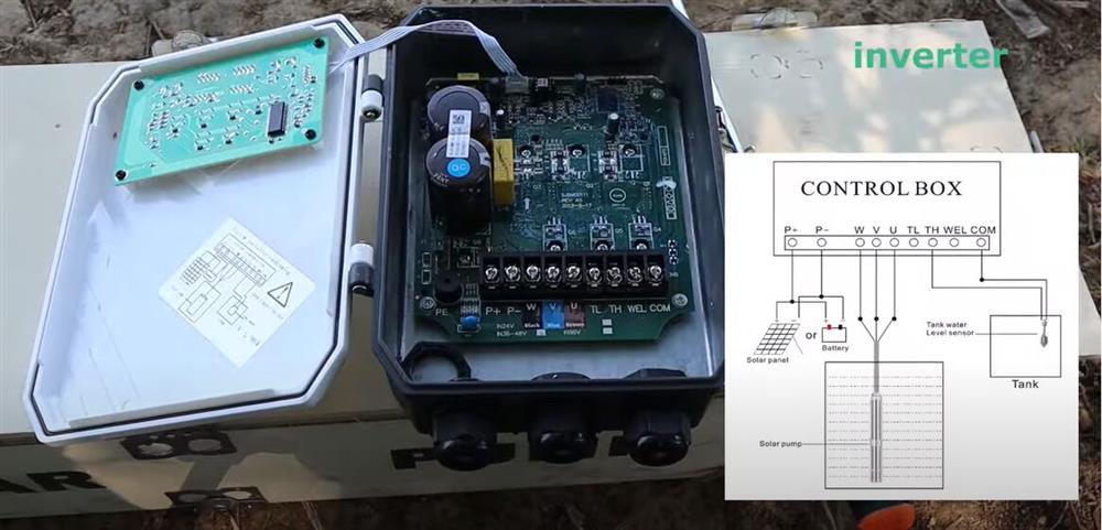
2.4. Basic System Architecture

The following illustration shows the basic application of this inverter.
It also includes the following devices to have a Complete running system.
– Generator or Utility
– PV modules

Consult with your system integrator for other possible system architectures depending on your requirements.

This inverter can power all kinds of appliances in a home or office environment, including motor-type appliances such as refrigerators and air conditioners.

SUN-29.930354050K-SG01HP3-EU-BM234 29.9-50kW Three Phase 234 MPPT Hybrid Inverter High Voltage Battery

3. Installation

3.1. Parts List (12)

SUN-5K6K8K10K12K-SG04LP3-EU size
Hybrid Inverter x1
Mounting bracket size for SUN-5K6K8K10K12K-SG04LP3-EU
Wall mounting bracket x1
Installation of Hybrid Inverter DEYE - Page 1
Stainless steel anti-collision-bolt M8x8Ox4
Installation of Hybrid Inverter DEYE - Page 1
Parallel communication cable x1
L-type Hexagon wrench x1
Battery temperature sensor x1
User manual x1
User manual x1
Wi-Fi-Plug (optional) x1
Meter (optional) x 1
Sensor Clamp x 3
Sensor Clamp x 3
DC+DC- Plug connectors including metal terminal xN
Sensor DC+DC- Plug connectors including metal terminal xN

3.2. Mounting instructions

Installation Precaution

This Hybrid inverter is designed for outdoor use(lP65), Please make sure the installation site meets the below conditions:

  • Not in direct sunlight
  • Not in areas where highly flammable materials are stored.
  • Not in potentially explosive areas.
  • Not in the cool air directly.
  • Not near the television Antenna or antenna cable.
  • Not higher than the altitude of about 2000 meters above sea level.
  • Not in an environment of precipitation or humidity (>95%)

Please AVOID direct sunlight, rain exposure, and snow laying up during installation and operation. Before connecting all wires, please take off the metal cover by removing
the screws as shown below:

SUN-5K6K8K10K12K-SG04LP3-EU

Considering the following points before selecting where to install:

  • Please select a vertical wall with load-bearing capacity for installation, suitable for installation on concrete or other non-flammable surfaces, installation is shown below.
  • Install this inverter at eye level in order to allow the LCD display to be read at all times.
  • The ambient temperature is recommended to be between -40~60“C to ensure optimal operation.
  • Be sure to keep other objects and surfaces as shown in the diagram to guarantee sufficient heat dissipation and have enough space for removing wires.
Installation of Hybrid Inverter DEYE - Page 1

For proper air circulation to dissipate heat, allow a clearance of approx. 50cm to the side and approx. 50cm above and below the unit. And 100cm to the front.

Mounting the inverter

Remember that this inverter is heavy! Please be careful when lifting out from the package. Choose the recommended drill head (as shown below pic) to drill 4 holes on the wall, 82-90mm deep.

  1. Use a proper hammer to fit the expansion bolt into the holes.
  2. Carry the inverter and hold it, make sure the hanger aims at the expansion bolt, and fix the inverter on the wall.
  3. Fasten the screw head of the expansion bolt to finish the mounting.
Inverter hanging plate installation

3.3 Battery connection

For safe operation and compliance, a separate DC over-current protector or disconnect device is required between the battery and the inverter. In some applications, switching devices may not be required but over-current protectors are still required. Refer to the typical amperage in the table below for the required fuse or circuit breaker size.

Model Wire Size Cablel (mm2) Torque value (max)
5 Kw 2 AWG 35 24.5 Nm
6/8 Kw 1 AWG 50 24.5 Nm
10/12 Kw 1/0 AWG 50 24.5 Nm
Chart 3-2 Cable size

All wiring must be performed by a professional person

Please follow the below steps to implement battery connection:

  1. Please choose a suitable battery cable with the correct connector which can well fit into the battery terminals.
  2. Use a suitable screwdriver to unscrew the bolts and fit the battery connectors in, then fasten the bolt by the screwdriver, making sure the bolts are tightened with a torque of 24.5 N.M in a clockwise direction.
  3. Make sure the polarity at both the battery and inverter is correctly connected.
Install SUN-5K6K8K10K12K-SG04LP3-EU
For the 5-12KW model, the battery connector screw size: M10
DC Battery Input 2/1AWG Wire Size
  1. In case of children touch or insects go into the inverter, Please make sure the inverter connector is fastened to a waterproof position by twisting it clockwise.

Installation must be performed with care.

Before making the final DC connection or closing DC breaker/disconnect, be sure positive(+) must be connected to positive(+) and negative(-) must be connected to negative(-). A reverse polarity connection on the battery will damage the inverter.

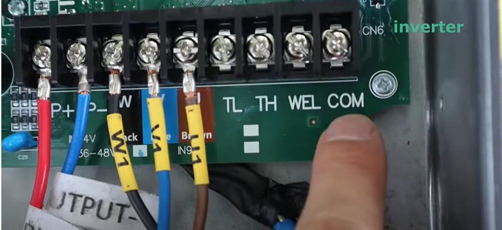
3.3.2 Function port definition

Inverter-Install

A

CN1:

  • TEMP (1,2): battery temperature sensor for the lead acid battery.
  • CT-L1 (3,4): current transformer (CT1) for “zero export to CT” mode clamps on L1 when in a three-phase system.
  • CT-L2 (5,6): current transformer (CT2) for “zero export to CT” mode clamps on L2 when in a three-phase system.
  • CT-L3 (7,8): current transformer (CT3) for “zero export to CT” mode clamps on L3 when in a three-phase system.

CN2:

  • G-start (1,2): dry contact signal for the startup of the diesel generator. When the “GEN signal” is active, the open contact (GS) will switch on (no voltage output).
  • G-valve (3,4): Dry contact output. When the inverter is in off-grid mode and the ”signal island mode” is checked, the dry contact will switch on.
  • Grid_Ry (5,6): reserved.
  • RSD (7,8): When the battery is connected and the inverter is in “ON” status, it will provide 12Vdc.
Inverter-Install Switching

B

  • Parallel A: Parallel communication port 1 (CAN interface)
  • Parallel B: Parallel communication port 2 (CAN interface)
  • Meter_485: for energy meter communication.
  • ModeBUS: Reserved.
  • BMS: BMS port for battery communication(CAN/RS48).

3.3.3 Temperature sensor connection for lead-acid battery

Inverter

3.4 Grid connection and backup load connection

  • Before connecting to the grid, please install a separate AC breaker between the inverter and the grid. Also, it is recommended that installs an AC breaker between the backup load and inverter. This will ensure the inverter can be securely disconnected during maintenance and fully protected from overcurrent. The recommended of AC breaker for the load port is 20A for 8kw, 32A for 10kw, and 32A for 12KW. The recommended of AC breaker for the grid port is 63A for 8kw, 63A for 10kw, and 63A for 12KW.
  • There are three terminal blocks with “Grid” “Load” and “GEN” markings. Please do not misconnect in ut and output connectors.
Model Wire Size Cablel (mm2) Torque value (max)
5/6/8/12 Kw 10 AWG 4 1.2 Nm
Backup load connection
Model Wire Size Cablel (mm2) Torque value (max)
5/6/8/12 Kw 10 AWG 6 1.2 Nm
Grid connection – Chart 3-3 Recommended Size for AC wires

Please follow the below steps to implement Grid, load and Gen port connection:

  1. Before making the Grid, load and Gen port connection, be sure to turn off the AC breaker or disconnector first.
  2. Remove the insulation sleeve 10 mm in length, unscrew the bolts, insert the wires according to the polarities indicated on the terminal block, and tighten the terminal screws. Make sure the connection is complete.
Grid, load and Gen port connection of Inverter

Be sure that the AC power source is disconnected before attempting to wire it to the unit.

  1. Then, insert AC output wires according to the polarities indicated on the terminal block and tighten the terminal. Be sure to connect corresponding N wires and PE wires to related terminals as well.
  2. Make sure the wires are securely connected.
  3. Appliances such as air conditioner are required at least 2-3 minutes to restart because it is
  4. required to have enough time to balance refrigerant gas inside the circuit. If a power shortage occurs and recovers in a short time, it will cause damage to your connected appliances. To prevent this kind of damage, please check with the manufacturer of the air conditioner if it is equipped with a time-delay function before installation. Otherwise, this inverter will trigger an overload fault and cut off output to protect your appliance but sometimes it still causes internal damage to the air conditioner.

3.5 PV Connection

Before connecting to PV modules, please install a separate DC circuit breaker between the inverter and PV modules. It is very important for system safety and efficient operation to use appropriate cable for PV module connection. To reduce the risk of injury, please use the proper recommended cable size as below.

Model Wire Size Cablel (mm2)
5/6/8/12 Kw 12 AWG 4
Chart 3-4 Cable size

To avoid any malfunction, do not connect any PV modules with possible current leakage to the inverter. For example, grounded PV modules will cause current leakage to the inverter. When using PV modules, please ensure the PV+ & PVof solar panel is not connected to the system ground bar.

It is requested to use the Pv junction box with surge protection. Otherwise, it will cause damage to the inverter when lightning occurs on PV modules.

3.5.1 PV Module Selection:

When selecting proper PV modules, please be sure to consider below parameters:

  1. Open circuit Voltage (Voc) of PV modules does not exceed the max. PV array open circuit voltage of the inverter.
  2. Open circuit Voltage (Voc) of PV modules should be higher than min. start voltage.
  3. The PV modules used to connect to this inverter shall be Class A rating certified according to IEC 61730.
Inverter Model 5 Kw 6 Kw 8 Kw 10 Kw 12 Kw
PV Input Voltage 550V (160V ~ 800V) 550V (160V ~ 800V) 550V (160V ~ 800V) 550V (160V ~ 800V) 550V (160V ~ 800V)
PV Array MPPT Voltage Range 200V ~ 650V 200V ~ 650V 200V ~ 650V 200V ~ 650V 200V ~ 650V
No. of MPP Trackers 2 2 2 2 2
No. of Strings per MPP Tracker 1+1 1+1 1+1 2+1 2+1
Chart 3-5

3.5.2 PV Module Wire Connection:

  1. Switch the Grid Supply Main Switch(AC)OFF.
  2. Switch the DC isolator OFF.
  3. Assemble the PV input connector to the inverter.

Safety Hint:
When using PV modules, please ensure the PV+ & PV- of the solar panel are not connected to the system ground bar.

Safety Hint:
Before connection, please make sure the polarity of the output voltage of PV array matches the “DC+” and “DC-” symbols.

Safety Hint:
Before connecting the inverter, please make sure the PV array open circuit voltage is within 1000V of the inverter.

Pic 5.1 DC+ male connector
Pic 5.2 DC- female connector

Safety Hint:
Please use an approved DC cable for the PV system.

Cable type Cross section (mmz)
Industry generic PV cable 4.0”6.0 (model: PV1-F) Range Recommended value
4.0”6.0
(12~10AWG)
4.0 (12AWG)

Chart 3-6The steps to assemble the DC connectors are listed as follows:
a) Strip off the DC wire about 7mm, and disassemble the connector cap nut (see picture 5.3)

Pic 5.3 Disassemble the connector cap nut

b) Crimping metal terminals with crimping pliers as shown in picture 5.4.

Pic 5.4 Crimp the contact pin to the wire

c) Insert the contact pin to the top part of the connector and screw up the cap nut to the top part of the connector. (as shown in picture 5.5)

Pic 5.5 connector with cap nut screwed on

d) Finally insert the DC connector into the positive and negative input of the inverter, like shown in picture 5.6

Pic 5.6 DC input connection

Warning:
Sunlight shines on the panel will generate voltage, high voltage in series may cause danger to life. Therefore, before connecting the DC input line, the solar panel needs to be blocked by the opaque material and the DC switch should be ‘OFF’, otherwise, the high voltage of the inverter may lead to life-threatening conditions.

Warning:
Please use its own DC power connector from the inverter accessories. Do not interconnect the connectors of different manufacturers.Max. DC input current should be 20A. if exceeds, it may damage the inverter and it is not covered by Deye warranty.

3.6 CT Connection

CT Connection

*Note: when the reading of the load power on the LCD is not correct, please reverse the CT arrow.

3.6.1 Meter Connection

Meter Connection
Meter Connection

Note:
When the inverter is in the off-grid state, the N line needs to be connected to the earth.

Note:
In the final installation, the breaker certified according to IEC60947-1 and IEC 60947-2 shall be installed with the equipment.

3.7 Earth Connection (mandatory)

Ground cable shall be connected to the ground plate on the grid side this prevents electric shock if the original protective conductor fails.

Earth Connection (mandatory)

3.8 WIFI Connection

For the configuration of the Wi-Fi Plug, please refer to the illustrations of the Wi-Fi Plug. The Wi-Fi Plug is not a standard configuration, it’s optional.

3.9 Wiring System for Inverter

This diagram is an example of an application that neutral connects with the PE in a distribution box.
For countries such as Australia, New Zealand, South Africa, etc., please follow local wiring regulations!

Wiring System for Inverter

3.10 Wiring diagram

This diagram is an example of an application in which neutral is separated from the PE in the distribution box/ For countries such as China, Germany, the Czech Republic, Italy, etc., please follow local wiring regulations!
Note: The backup function is optional in the German market. Please leave the backup side empty if the backup function is not available in the inverter.

Wiring diagram
Installation of Hybrid Inverter DEYE - Page 1

1) DC Breaker for battery
SUN 5K—SG—EU: 150A DC breaker
SUN 6K—SG—EU: 200A DC breaker Backup Load
SUN 8K—SG—EU: 250A DC breaker
SUN 10K—SG—EU: 300A DC breaker
SUN 12K—SG—EU: 300A DC breaker
2) AC Breaker for backup load
SUN SK—SG—EU: 16A AC breaker
SUN 6K—SG—EU: 16A AC breaker
SUN 8K—SG—EU: 20A AC breaker
SUN 10K—SG—EU: 32A AC breaker
SUN 12K—SG—EU: 32A AC breaker
3) AC Breaker for grid
SUN 5K—SG—EU: 63A AC breaker
SUN 6K—SG—EU: 63A AC breaker
SUN 8K—SG—EU: 63A AC breaker
SUN 10K—SG—EU: 63A AC breaker
SUN 12K—SG—EU: 63A AC breaker
4) AC Breaker for home load
Depends on the household loads

3.11 Typical application diagram of diesel generator

Max. 10pcs parallel for on-grid and off-grid operation.

Installation of Hybrid Inverter DEYE - Page 1

4. OPERATION

4.1 Power ON/OFF

Once the unit has been properly installed and the batteries are connected well, simply press the On/Off button (located on the left side of the case) to turn on the unit. When the system is without a battery connected, but connected with either PV or grid, and the ON/OFF button is switched off, LCD will still light up (Display will show OFF), In this condition, when switching on the ON/OFF button and selecting NO battery, the system can still work.

4.2 Operation and Display Panel

The operation and display panel, shown in the below chart, is on the front panel of the inverter. It includes four indicators, four function keys, and an LCD display, indicating the operating status and input/output power information.

LED Indicator Messages
DC Green-led solid light PV Connection normal
AC Green-led solid light Grid Connection normal
Normal Green-led solid light Inverter operating normally
Alarm Red-led solid light Malfunction or warning
Chart 4-1 LED indicators
Function Key Description
Esc To exit the setting mode
Up To go to the previous selection
Down To go to the next selection
Enter To confirm the selection


How to Install a Solar Water Pump Step-by-Step Guide

In the pursuit of sustainable and cost-effective water pumping solutions, transitioning to solar-powered water pumps stands out as an environmentally conscious choice. We will be going through the step-by-step installation process for solar water pumps in a detailed manner. We shall also look into the common questions regarding installation and maintenance as well.

When it comes installing a Solar Water Pump, it consist of a 4 step process, lets look into it one by one

Step 1: Site Selection and Sun Exposure

Choose a location that receives maximum sunlight exposure throughout the day. Confirm that the site allows for proper orientation and angle adjustment of the solar panels to capture the most sunlight. Proper sun exposure is very much important for the efficiency of the entire solar water pump system.

Step 2: Proper Sizing of the Solar Water Pump System

  1. Determine Water Requirements: Identify the specific water needs of your application, whether it’s for irrigation, domestic use, or other purposes. Accurately calculate the volume of water required to ensure the solar water pump system is appropriately sized.
  2. Match Solar Panel Capacity: Align the solar panel capacity with the power requirements of the pump. This matching ensures that the system operates efficiently, harnessing sufficient solar energy to power the pump effectively.

Step 3: Quality Components and Professional Installation

  1. Invest in High-Quality Components: Choose reliable and durable components for your solar water pump system, including the pump itself, solar panels, controller, and any additional accessories. High-quality components contribute to the system’s long lasting performance
  2. Consider Professional Installation: If you are not familiar with electrical and plumbing work, it is advisable to hire a professional installer, who could set the system correction and reduce the risk of error or malfunctions

Step 4: Battery Storage for Continuous Operation

  1. Assess System Design: Determine if your solar water pump system is intended for intermittent or emergency use. If so, consider integrating a battery storage system to ensure continuous operation during periods of low sunlight or power outages.
  2. Properly Size and Configure Battery Bank: Ensure that the battery bank is appropriately sized to meet the pump’s power requirements. Upon installation ensure the batter system can provide necessary back up

Can I Install a Solar Water Pump Directly to the Solar Panel?

Connecting a solar water pump directly to the solar panel is not advisable. Atlthough it may seem convenient, but it can lead to issues and may affect the lifespan of the Solar

Solar pump. Its is best to use a control unit.

Here’s why:

  1. Voltage Regulation: Solar panels generate varying voltages based on sunlight intensity. Connecting the pump directly to the solar panel without regulation can expose the pump to fluctuating voltage levels, potentially causing damage over time.
  2. Control Unit Functionality: A control unit regulates the power flow from the solar panels to the pump, ensuring a stable and consistent supply of energy. It protectthe pump from being overloaded or damaged due to power fluctuations.
  3. Optimal Performance: Using a control unit allows for better control and optimization of the solar water pump system. It ensures that the pump receives the right amount of power, maximizing efficiency and performance.

When installing a solar water pump, always follow the manufacturer’s guidelines and recommendations. Including a control unit in your system is a crucial step to safeguard the pump and ensure a trouble-free operation. If you are uncertain about the installation process or lack experience in electrical work, it is advisable to seek the assistance of a professional installer to guarantee a correct and secure setup.

What Are the Key Steps to Install a Solar Water Pump?

Breaking down the installation process into key steps provides a clear roadmap for those venturing into solar water pump installation. Starting with the site assessment, then moving on to component assembly, water source connection, and solar panel integration, this step-by-step approach simplifies the process. Emphasize the importance of adhering to the manufacturer’s guidelines at each stage for optimal results. ​
Installing a solar water pump involves several key steps to ensure a successful and efficient setup. Here is a comprehensive guide to walk you through the process:

1. Site Assessment:

Begin by selecting a location that receives maximum sunlight exposure throughout the day. This ensures optimal energy production for the solar panels. Confirm that the chosen site allows for proper orientation and angle adjustment of the solar panels to capture the most sunlight.

2. Water Requirement Determination:

Identify the specific water requirements for your intended application, whether it’s for irrigation, domestic use, or other purposes. Calculate the volume of water needed to determine the appropriate size for the solar water pump system.

3. Solar Panel Sizing:

Match the solar panel capacity to the power requirements of the pump. It ensures that the solar water pump system operates efficiently by using sufficient solar energy to power the pump

4. Component Assembly:

Assemble the necessary components, including the solar pump, solar panels, controller, and any additional accessories. Follow the manufacturer’s guidelines carefully during this process to ensure proper integration and functionality.

5. Water Source Connection:

Establish a water source for the pump, whether it involves digging a borewell or tapping into an existing water supply. Connect the pump to the water source, ensuring a secure and leak-free connection.

6. Solar Panel Integration:

Connect the solar panels to the solar water pump system. Verify that the panels are correctly positioned and oriented for maximum sunlight absorption. Follow the provided instructions to connect the panels to the controller and pump.

7. Control Unit Installation:

Include a control unit in your system to regulate the power flow from the solar panels to the pump. The control unit acts as a protective measure, preventing the pump from damage due to voltage irregularities and ensuring optimal performance.

8. Testing and Calibration:

Before putting the system into full operation, conduct thorough testing. Check for any leaks, confirm that the pump is working correctly, and ensure the control unit is regulating power effectively. Calibrate the system as needed to address any issues.

9. Regular Maintenance:

Implement a routine maintenance schedule to keep the solar water pump system in optimal condition. Tasks may include cleaning solar panels, checking connections, inspecting the pump, and ensuring the control unit is functioning correctly.

4. How Long Does It Take to Install a Solar Water Pump?

The duration of a solar water pump installation varies based on factors such as the installer’s experience, site conditions, and system complexity. On average, a professional installer may complete the setup in one to two days. This timeframe underscores the efficiency and relatively quick implementation of solar water pump systems. ​

The duration of installing a solar water pump can vary based on several factors, including the complexity of the system, the installer’s experience, site conditions, and the specific requirements of the installation. On average, a professional installer can complete the installation process within one to two days.

Here is a breakdown of the factors influencing the installation timeline:

  1. System Complexity: The complexity of the solar water pump system, including the number of components, the need for additional accessories, and the sophistication of the control unit, can impact the installation time.
  2. Installer Experience: The expertise and experience of the installer play a significant role. A seasoned professional with prior experience in solar water pump installations is likely to complete the process more efficiently than someone with less experience.
  3. Site Conditions: The characteristics of the installation site, such as accessibility, terrain, and proximity to the water source, can affect the installation timeline. Sites with challenging conditions may require more time for proper setup.
  4. Preparedness and Planning: Adequate preparation, including having all necessary components on hand and a well-thought-out installation plan, can contribute to a faster and smoother installation process.
  5. Size of the System: The size and capacity of the solar water pump system also factor into the installation time. Larger systems may involve more components and connections, requiring additional time for assembly and configuration.

How to Install Solar Water Pump with Battery?

Solar water pumps are specially designed to utilize DC electricity from solar panels. The pumps must work during low light conditions, when power is reduced, without stalling or overheating. Low volume pumps use positive displacement (volumetric) mechanisms which seal water in cavities and force it upward. The submersible pump can realize working at sunrise and resting at sunset, no need any person look after it, no need diesel, no need power grid, and can be used with irrigation equipments to save water, energy and cost.

So, today we will talk about how to install a solar water pump with battery.

Wiring

  1. Connecting the power cable of the motor to the W, V and U terminals.
  2. Conneting the DC power supply to P+, P-, (battery or solar panel).

Wiring diagram of solar water pump

How to install the solar water pump with battery?

  1. We using a 48VDC battery, connecting the connector to the solar water pump outlet. If the pump will be put in deep water, it shold be lifted by ropes. (Becareful not to use the power cable to lift pump).
  2. Putting the pump into the water. When in pond/ pool/ river/ lake, the water inlet of the pump must below the water level.
  3. When the solar pump is putting into a narrow deep well, the water inlet of the pump should be 7-8 meters lowers than the water level so that the pump can pump enough water. The controller automatically recognizes that the pump is connected the battery or solar panel.
  4. Then press”ON”, the controller starts to work.
  5. Press “switch” to view the current speed. The outlet bagan to spray water.
  6. Press ▼ to decrease the motor speed. (When the power supply is battery.)
  7. Press “Enter” to confirm the setting. Then the water discharge is obviously reduced. The mimimum speed that canbe set is 1000 rpm.
  8. Switching to check the current is 0.7A, power is 38W, and voltage is 49.9V.
  9. Press the “OFF” to stop pumping. (When the power supply is solar penel, the pump will automatically start or stop).
  10. Connect the level snesor according to the wiring diagram. It is often used in water tanks. The level sensor is onnected to the TH and COM terminals.How to install solar water pump with battery

When the float switch is lifted by water, the pump stops working. The TANK indicator light on the controller panel is always on. After 30 minutes, the solar water pump will automatically restart and pump water.

If you want to know more details about the installing

 solar water pump with battery, please check the video below.